TM 1-1670-260-12&P
0016 00
__________________________________________________________________________________________
(5) Place free sling eye from yellow/white sling attached to the 8 o’clock position blade retention
assembly onto the clevis part of the shackle assembly.
(6) Place the midpoint of both adjustable length tie-down slings attached to the topside of the blade
sleeves onto the clevis part of the shackle assembly.
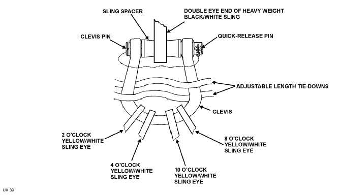
Figure 5. Rigging Shackle Assembly
CAUTION
Ensure that the sling spacer is installed when the
shackle assembly is assembled.
(7) Place double eye end of heavy weight black/white sling (12), Figure 1, View A, to shackle assembly
(Figure 5) and secure shackle assembly as follows:
(a) Insert sling spacer from shackle assembly into the double eye end opening of heavy weight
black/white sling.
(b) Align the holes in the shackle assembly clevis with hole in sling spacer.
(c) Once holes are aligned, insert clevis pin through holes in shackle assembly clevis and sling spacer.
(d) Insert quick-release pin through hole in base of the clevis pin to secure the clevis pin in the clevis.
h. Carefully lay the rigged shackle assembly on the helicopter, and heavy weight black/white sling to the side that
the recovery helicopter will approach from.
0016 00-11