TM 1-1500-204-23-5
NOTE
Ground runup shall be performed by
authorized personnel only.
(b) Start engine in accordance with
applicable maintenance manual. Run engine with pedals
in neutral position. Reset marking device on underside of
tailboom assembly. Slowly move marking device into
disk of tail rotor approximately one inch from tip.
(c) When near blade is marked, stop
engine and allow rotor to stop. Repeat this procedure
until tracking mark crosses over to the other blade, then
extend pitch control link of unmarked blade one half turn.
(2) Electronic method. The electronic
VIBREX balancing and tracking kit is housed in a carrying
case and consists of a Model 177M-6A Balancer, a Model
135M-11
Strobex,
track
and
balance
charts,
an
accelerometer, cables, and attaching brackets. The
VIBREX balancing kit is used to measure and indicate the
level of vibration induced by the main rotor and tail rotor
of a helicopter. The VIBREX analyzes the vibration
induced by out-of-track or out-of-balance rotors, and then
by plotting vibration amplitude and clock angle on a chart
the amount and location of rotor track or weight change is
determined. In addition, the VIBREX is used in
troubleshooting by measuring the vibration levels and
frequencies or revolutions per minute (RPM) of unknown
disturbances. The main units of the VIBREX are the
Balancer/Phazor 177M6A, Strobex Tracker 135M11, and
VIBREX Tester II. The primary airframe mounted
components are three Accelerometers 4177B and two
Magnetic Pickups 3030AN. Refer to TM 55-4920-402-13
for detailed operating instructions.
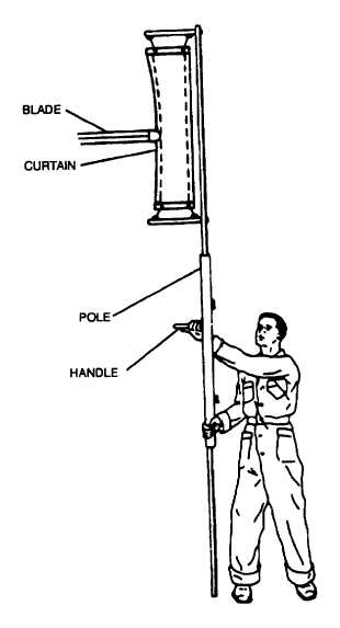
Figure 3-9. Rotor Blade Tracking
Table 3-2. Helicopter Vibration Types
Frequency level
Vibration
Extreme low frequency
Low frequency
Medium frequency
High frequency
Less than 1/rev PYLON ROCK
1/rev or 2/rev type vibration
Generally 4, 5, or 6/rev
Tail rotor speed or faster
Change 2 3-13


