*TM 1-1500-204-23-5
Change 3
3-5
3-5 Helicopter Flight Controls. The various helicop-
ter controls are explained in the following paragraphs.
a.
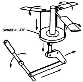
Cyclic Pitch Control. The cyclic pitch control
changes the tilt of the main rotor for control about the
longitudinal axis (roll) and lateral axis (pitch). It acts
through a mechanical linkage, as shown in figure 3-4, to
increase the pitch of the retreating blade and decrease
the pitch of the advancing blade on each cycle of rotation.
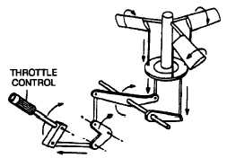
b.
Collective Pitch Control. The collective pitch
control, as shown in figure3-5, varies the lift of the main
rotor by increasing or decreasing the pitch of all blades
at the same time. Raising the collective pitch control
increases the pitch of the blades, thereby increasing the
lift. Lowering the control decreases the pitch of the
blades, causing a loss of lift. Collective pitch control is
also used in coordination with cyclic pitch control to regu-
late the airspeed of the helicopter.
c.
Swashplate. The swashplate assembly trans-
mits movement of the flight controls to the main rotor
blades. Refer to the applicable maintenance manual for
unique features of a swashplate on a specific aircraft.
d.
Throttle Control. The throttle control is mounted
on the collective pitch grip, as shown in figure 3-5, and is
operated by rotating the motorcycle--type grip. Rotating
the grip outboard increases rpm, and rotating it inboard
decreases rpm.
e.
Torque Control. Torque control provides for
movement about the vertical axis (yaw). This movement
is controlled by the directional--control pedals in the cock-
pit.
Figure
3-4. Cyclic Pitch Control.
3-6 Main Rotor Assemblies.
Rigid, semi--rigid, and
fully articulated rotor assemblies are described in the
following paragraphs.
a.
Semi--Rigid Rotor. In a semi--rigid rotor system,
the rotor blades are rigidly interconnected to the hub, but
the hub is free to tilt and rock with respect to the rotor
shaft. In this system, only two--bladed rotors are used.
The rotor flaps as a unit, that is, as one blade flaps up, the
other blade flaps down an equal amount.
b.
Fully Articulated Rotor. Fully articulated rotor
systems permit individual movement of the blades from
the hub in both a vertical and horizontal plane. The hinge
points and direction of motion around each hinge are
shown in figure 3-6.
(1)
Blade flapping. The rotor blades are at-
tached to the rotor hub by a horizontal hinge which per-
mits the blades to move in a vertical plane, and flap up
or down, as they rotate, as shown in figure 3-8. In forward
flight and assuming that the blade--pitch angle remains
constant, the increased lift on the advancing blade will
cause the blade to flap up, decreasing the angle of attack
because the relative wind will change from a horizontal
direction to a more downward direction. The decreased
lift on the retreating blade will cause the blade to flap
down, increasing the angle of attack
Figure
3-5. Collective Pitch Control.