TM 1-1270-476-30
4-73
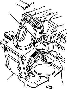
4-5. NIGHT SENSOR ASSEMBLY (NSA) REPAIR (cont)
CAUTION
Scanner optics assembly must be manually
supported when capscrews are removed to
prevent damaging wires and flexible
harnesses.
NOTE
Two people are required to perform steps (3)
thru (7) below.
(3) Manually support scanner optics
assembly (1) and remove four socket
head capscrews (8) and washers (9)
securing it to night sensor assembly.
Use hex key T1 to remove lower right
hand screw.
(4) Carefully move scanner optics
assembly (1) downward approximately
1-inch and tilt top slightly forward to
gain access to connector W10P13 (10).
(5) Remove screw (11) and disconnect
connector W10P13 (10) from connector
A32RTJ1.
CAUTION
Be very careful not to stretch, nick, or crease
flexible harness when disconnecting
connectors.
(6) Disconnect connectors A23P1 (12) and
A23P2 (13) by loosening four
screwlocks (14).
(7) Remove scanner optics assembly and
place in a safe place.
8
9
14
12
14
13
10
1
220-320A
11