TM 1-1270-476-30
4-237
4-29. CONTROL PANEL ASSEMBLY 2A1 REPAIR (cont)
5. RESISTOR R4 OR R5 REPLACEMENT
NOTE
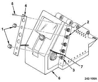
This procedure is for replacing resistor R4 (2)
and can be also used for replacing resistor R5
(3).
REMOVAL
a. Remove HOD assembly (1 above).
b. Remove knob assemblies (1) by loosening
setscrews securing knobs to shafts of
resistor R4 (2) and resistor R5 (3).
NOTE
Illuminated panel assembly A2 wires are black.
c. Cut lacing and tying tape securing
illuminated panel assembly A2 lead wires to
internal wire bundle.
d. Remove illuminated panel assembly A2 (4)
by removing two mounting screws (5) and
lifting illuminated panel assembly A2 from
control panel assembly housing (6).
e. Pull panel wires (7) far enough through
housing to lay illuminated panel assembly
A2 (4) aside.