TM 55-1680-320-23 & P
3-15. BOOM HEAD ASSEMBLY - REPAIR (cont)
3-15
5.
a.
b.
c.
d.
e.
f.
g.
Reassembly.
Place electrical braid over both leads of actua-
tor assembly, Route shielded leads through
access hole in boom head housing.
Slide approximately 10 inches (25.4 cm)
of heat shrink tubing over cable cutter and ac-
tuator wires until it butts against housing,
Shrink tubing in place.
Slide connector shell, insulator, approximately
5 inches (12.7 cm) of heat shrink tubing, and
3 inches (7.62 cm) of electrical braid onto wire
harness (29) and thermal switch connector
wiring.
Install pins into connector (79) in accordance
with wiring diagram.
Assemble connector (79). Slide electri-
cal braid flush with connector and twist braid
until secured. Slide heat shrink tubing over
braid and shrink tubing in place.
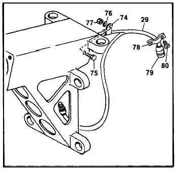
Install clamp (78) onto connector (79) and
secure using screws (80).
Secure wire harness (29) to boom head housing
using clamp (74), bolt (75), washer (76) and
nut (77).
GO TO NEXT PAGE
3-60