TM 55-1680-320-23 & P
3-11. RESCUE HOIST - ADJUST (cont)
3-11
c.
d.
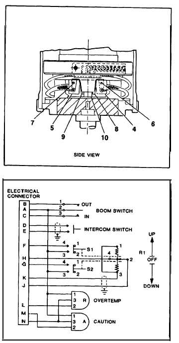
If switches S1 or S2 (4, 5) were placed or
electrical wiring repaired, check continuity as
follows:
(1)
(2)
If a
Disconnect electrical plug P5 from con-
nector J5 on control panel assembly.
Using a multimeter, check continuity be-
tween pins A and C on plug P5 while
actuating switches S2 and S3 (5, 11).
NOTE
fault is detected, replace or repair
defectivecomponent before
continuing.
(3)
(4)
Check continuity between pins B and C
on plug P5 while actuating switches S1
and S4 (4, 12).
Connect electrical plug P5 to connector
J5 on control panel.
Loosen screws (6, 7). Adjust switches S1
and S2 (4, 5) and actuators (8, 9) for 0.05
inch (1.27 cm) clearance on each side of ac-
tuating lever (10). Tighten screws (6, 7).
GO TO NEXT PAGE
3-42

