TM 1-1670-260-12&P
0015 00
__________________________________________________________________________________________
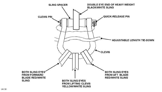
Figure 3. Rigging Shackle Assembly
g. Carefully lay the rigged shackle assembly on the helicopter and heavy weight black/white sling to the side that
the recovery helicopter will approach from.
WARNING
Failure to arrange sling eyes on the sling link assembly
as shown in Figure 1, View E, will create an unbalanced
load on the sling link assembly and may cause the
assembly to open as tension is applied to the slings.
h. Connect the double eye end of heavy weight black/white sling (8), Figure 1, view A, to the single eye end of
sling (6) using sling link assembly (7).
(1) Verify that arrangement of sling eyes is as shown in View E, with sling (8) in Position A orientation.
(2) Extend sling (8) out away from the damaged helicopter for easy access during the recovery
helicopter hook-up procedure covered in Paragraph 7 of this WP.
NOTE
In a non-tactical situation recommend removal of tail rotor
blades prior to recovery or tail rotor blade post recovery
inspection shall be performed.
i.
To prevent tail rotor blade flapping tie the lower blade from the tail rotor to the helicopter using a fixed length
tie-down (without snap hook).
0015 00-9