
TM 1-1500-204-23-11
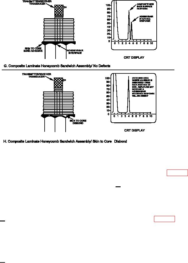
Figure 5-2. Pulse-Echo Ultrasonic Inspection with A-Scan Presentation (Sheet 3 of 3)
(b) Through-Transmission Ultrasonics. T-
access to both sides of the part and alignment of
his technique uses two transducers, one to transmit
the two transducers during inspection to ensure the
sound energy and one to receive. Sound energy is
receiving transducer picks up the sound energy sent
sent from one side of the part through the part to
by the transmitting transducer (see igure 5-3, View
the second transducer on the opposite side. Unlike
B).
pulse-echo ultrasonics, sound does not have to tra-
3 Test
Display. Through-transmission
verse the thickness of the part twice. A defect
test results may be displayed in two basic ways
encountered in the part signiicantly reduces the inten-
when using a display or permanent image recorder.
sity of the sound energy. This reduction in sound
The A-scan presentation measures the amplitude of
energy intensity is used to detect the presence of
the transmitted and received energy. It reveals the
defects. It can be used to determine the area of a
presence of the laws and provides some indication
defect.
of its relative size but does not locate its depth from
the surface of the part. See igure 5-3, View C for
1 Equipment Required. Required equip-
typical through-transmission A-scan presentation CRT
ment includes a pulsed ultrasonic generator, sending
responses for the defects indicated. The C-scan
and receiving transducers located on opposite sides
presentation requires automated scanning of the test
of the test article, and a signal processing and display
article and the use of signal processing techniques.
device. A coupling medium is required. For contact
A digital image display or paper recorder is used
testing methods, a thin layer of luid is generally used.
to display ultrasonic test responses. The C-scan
This requires that the surface of the test article be
provides a plan view of the article, revealing the area
clean and relatively smooth.
of the law but providing no information relative to
2 Limitations. Through-transmission ultr-
its depth or distance from the surface. Successive
asonics is usually more sensitive for law detection
C-scans with signal gates set to various depths below
in bonded assemblies. This technique is not able to
the surface may be used to locate the law in a
determine defect depth or type. In addition, it requires
section.
5-8