TM 55-1680-320-23 & P
2-48. WINCH ASSEMBLY - REPAIR (cont)
2-48
a.
b.
c.
d.
e.
f.
g
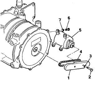
Remove chain guard cover (1) by removing
screws (2) and washers (3).
NOTE
Prior to disconnecting chain (4) from
limit switch drive assembly (7), mark
sprocket on limit switch and winch
assembly to preserve timing and
prevent need for adjustment.
Remove chain (4) by removing master link.
Remove limit switch drive assembly (5) by
removing screws (6) and washers (7).
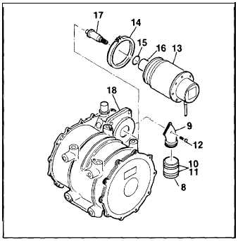
Disconnect motor electrical connector from
control panel.
Remove boot (8) from motor airduct (9) by
removing clips (10) and bands (11 ). Remove
motor airduct by removing bolts (12).
Remove motor (13) by releasing coupling
(14).
Remove packing (15) from motor flange (16).
Discard packing. Remove inertia dump as-
sembly (17) from adapter plate (18).
GO TO NEXT PAGE
2-99