
0080
TM 1-1740-221-13&P&P
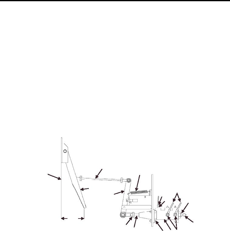
HYDRAULIC MASTER CYLINDER (BRAKES) - (CONTINUED)
NOTE
Plunger (Figure 1, Item 9) will drop as master cylinder is withdrawn from mounting hole.
5.
Disconnect brake valve luid tubing (Figure 1, Item 6) from the brake master cylinder and install caps and
plugs to prevent spillage.
6.
Disconnect brake hoses from brake master cylinder and install cap and plugs for reservoir hoses
(Figure 1, Item 3).
7.
Remove bolt and lock nut (not shown) from torque arm rod (Figure 1, Item 11) and discard lock nut.
NOTE
Requires one person to secure bolt while other person removes lock nuts under the front
of vehicle
8. Remove three bolts (two shown), lat washers and lock nuts (Figure 1, Item 8) and discard lock nut.
9. Remove master cylinder (Figure 1, Item 7).
10. Disconnect threaded rod (Figure 1, Item 9) and jam nut (Figure 1, Item 10) from brake master cylinder
(Figure 1, Item 7).
1
FRONT CAB
2
WALL
12
5
3
11
4
4
8.25
PEDAL CLEARANCE
3
10
9
6
7
8
WP0071F1
Figure 1. Hydraulic Master Cylinder (Brakes) (Inspection, Removal and Installation)
11. Disconnect ittings (Figure 1, Item 4) from the brake master cylinder and store them for future installation
(discard over-rings).
END OF TASK
INSTALLATION
WARNING
Before servicing brake system components, make sure that the machine is on level ground. Set
the parking brake. Put chocks on each side of all four wheels. Disconnect the battery so that the
engine cannot be started. If you do not take these precautions, the machine could run you over.
00802

