
0014 00
TM 1-1730-213-13&P
INSPECTION OF INSTALLED ITEMS CONTINUED
2.
Linkage pivot holes for visible elongation.
3.
Pins for wear grooves.
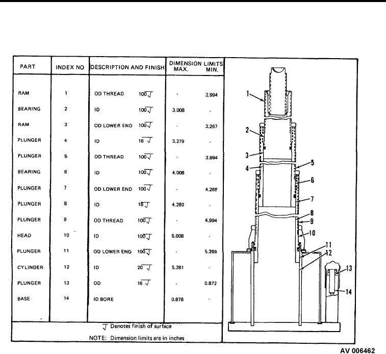
Figure 3.
Table of limits.
4.
Surface of plunger for scratches or nicks. Check diameter according to the table of limits (Figure 3).
5.
Threads for damage.
6.
Spring (Figure 2, Item 22) load of 64 + 4 pounds at 0.675 inch in length.
7.
Spring (Figure 2, Item 15) load of 3/8 to 3/4 pound at 1 3/4 inch free length.
8.
Tips of needle (Figure 2, Item 23) and valve body (Figure 2, Item 25) for wear or scratches.
9.
Balls bearing (Figure 2, Item 7) and (Figure 2, Item 16) and ball seats for roughness.
10. Screen for clogging or bending.
END OF WORK PACKAGE
0014 00-4

